34. Intel Virtual Function Driver
Supported Intel® Ethernet Controllers (see the DPDK Release Notes for details) support the following modes of operation in a virtualized environment:
SR-IOV mode: Involves direct assignment of part of the port resources to different guest operating systems using the PCI-SIG Single Root I/O Virtualization (SR IOV) standard, also known as “native mode” or “pass-through” mode. In this chapter, this mode is referred to as IOV mode.
VMDq mode: Involves central management of the networking resources by an IO Virtual Machine (IOVM) or a Virtual Machine Monitor (VMM), also known as software switch acceleration mode. In this chapter, this mode is referred to as the Next Generation VMDq mode.
34.1. SR-IOV Mode Utilization in a DPDK Environment
The DPDK uses the SR-IOV feature for hardware-based I/O sharing in IOV mode. Therefore, it is possible to partition SR-IOV capability on Ethernet controller NIC resources logically and expose them to a virtual machine as a separate PCI function called a “Virtual Function”. Refer to Fig. 34.1.
Therefore, a NIC is logically distributed among multiple virtual machines (as shown in Fig. 34.1), while still having global data in common to share with the Physical Function and other Virtual Functions. The DPDK fm10kvf, iavf, igbvf or ixgbevf as a Poll Mode Driver (PMD) serves for the Intel® 82576 Gigabit Ethernet Controller, Intel® Ethernet Controller I350 family, Intel® 82599 10 Gigabit Ethernet Controller NIC, Intel® Fortville 10/40 Gigabit Ethernet Controller NIC’s virtual PCI function, or PCIe host-interface of the Intel Ethernet Switch FM10000 Series. Meanwhile the DPDK Poll Mode Driver (PMD) also supports “Physical Function” of such NIC’s on the host.
The DPDK PF/VF Poll Mode Driver (PMD) supports the Layer 2 switch on Intel® 82576 Gigabit Ethernet Controller, Intel® Ethernet Controller I350 family, Intel® 82599 10 Gigabit Ethernet Controller, and Intel® Fortville 10/40 Gigabit Ethernet Controller NICs so that guest can choose it for inter virtual machine traffic in SR-IOV mode.
For more detail on SR-IOV, please refer to the following documents:
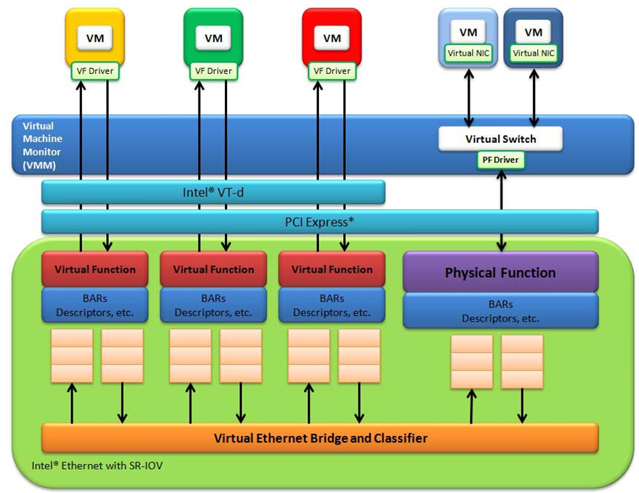
Fig. 34.1 Virtualization for a Single Port NIC in SR-IOV Mode
34.1.1. Physical and Virtual Function Infrastructure
The following describes the Physical Function and Virtual Functions infrastructure for the supported Ethernet Controller NICs.
Virtual Functions operate under the respective Physical Function on the same NIC Port and therefore have no access to the global NIC resources that are shared between other functions for the same NIC port.
A Virtual Function has basic access to the queue resources and control structures of the queues assigned to it. For global resource access, a Virtual Function has to send a request to the Physical Function for that port, and the Physical Function operates on the global resources on behalf of the Virtual Function. For this out-of-band communication, an SR-IOV enabled NIC provides a memory buffer for each Virtual Function, which is called a “Mailbox”.
34.2. Intel SR-IOV drivers
34.2.1. Intel® Ethernet Adaptive Virtual Function
Adaptive Virtual Function (IAVF) is a SR-IOV Virtual Function with the same device id (8086:1889) on different Intel Ethernet Controller. IAVF Driver is VF driver which supports for all future Intel devices without requiring a VM update. And since this happens to be an adaptive VF driver, every new drop of the VF driver would add more and more advanced features that can be turned on in the VM if the underlying HW device supports those advanced features based on a device agnostic way without ever compromising on the base functionality. IAVF provides generic hardware interface and interface between IAVF driver and a compliant PF driver is specified.
Intel products starting Ethernet Controller 700 Series to support Adaptive Virtual Function.
The way to generate Virtual Function is like normal, and the resource of VF assignment depends on the NIC Infrastructure.
For more detail on SR-IOV, please refer to the following documents:
34.2.1.1. IAVF PMD parameters
watchdog_periodThe reset watchdog is enabled when link state changes to down. The default period is 2000us, defined by
IAVF_DEV_WATCHDOG_PERIOD. Setdevargsparameterwatchdog_periodto adjust the watchdog period in microseconds, or set it to 0 to disable the watchdog, for example,-a 18:01.0,watchdog_period=5000or-a 18:01.0,watchdog_period=0.auto_resetVF auto-reset is enabled by default, meaning the driver will attempt to bring the VF back up transparently after a reset event, rather than relying on the application to do so. To disable this functionality, set the
auto_resetdevarg to zero:-a 18:01.0,auto_reset=0auto_reconfigRestore settings (unicast and multicast promiscuous states) on the VF after a reset event. Enabled by default. To disable it:
-a 18:01.0,auto_reconfig=0no-poll-on-link-downStop polling Rx/Tx hardware queue when link is down. This is enabled by default because it is required when
auto_resetis enabled which it is by default. To disable it, you must disable bothauto_resetandno-poll-on-link-down, for example,-a 18:01.0,auto_reset=0,no-poll-on-link-down=0.mbuf_checkSet the
devargsparametermbuf_checkto enable Tx diagnostics. For example,-a 18:01.0,mbuf_check=<case>or-a 18:01.0,mbuf_check=[<case1>,<case2>...]. Thereafter,rte_eth_xstats_get()can be used to get the error counts, which are collected intx_mbuf_error_packetsxstats. In testpmd these can be shown via:testpmd> show port xstats all. Supported values for thecaseparameter are:mbuf: Check for corrupted mbuf.size: Check min/max packet length according to HW spec.segment: Check number of mbuf segments does not exceed HW limits.offload: Check for use of an unsupported offload flag.
34.2.1.2. HW-Specific Notes For IAVF
Intel® 700 Series Ethernet devices:
To use DPDK IAVF PMD the device id (0x1889) need to specified during device assignment in hypervisor. For example, on qemu, the device assignment should carry the IAVF device id (0x1889) like
-device vfio-pci,x-pci-device-id=0x1889,host=03:0a.0.
Intel® E800 Series Ethernet devices:
the “Protocol Extraction” feature which is supported by ice PMD is also available for IAVF PMD. The same devargs with the same parameters can be applied to IAVF PMD. for Detail please reference the section
Protocol extraction for per queueof ice.rst.Quanta size configuration is supported by setting
devargsparameterquanta_size, for example:-a 18:00.0,quanta_size=2048. The default value is 1024, and quanta size should be set as the product of 64 in legacy host interface mode.When using the Intel out-of-tree “ice” PF/kernel driver v1.13.7 or later, to create VFs with >16 queues (aka. “large VFs”), it is necessary to change the rss_lut_vf_addr setting in sysfs from the default of 64 to 512. This can be done using the following command for the first VF on an interface:
echo 512 > /sys/class/net/<PF interface>/device/virtfn0/rss_lut_vf_attr
34.2.2. The PCIE host-interface of Intel Ethernet Switch FM10000 Series VF infrastructure
In a virtualized environment, the programmer can enable a maximum of 64 Virtual Functions (VF) globally per PCIE host-interface of the Intel Ethernet Switch FM10000 Series device. Each VF can have a maximum of 16 queue pairs. The Physical Function in host could be only configured by the Linux* fm10k driver (in the case of the Linux Kernel-based Virtual Machine [KVM]), DPDK PMD PF driver doesn’t support it yet.
For example,
Using Linux* fm10k driver:
rmmod fm10k (To remove the fm10k module)
insmod fm0k.ko max_vfs=2,2 (To enable two Virtual Functions per port)
Virtual Function enumeration is performed in the following sequence by the Linux* pci driver for a dual-port NIC. When you enable the four Virtual Functions with the above command, the four enabled functions have a Function# represented by (Bus#, Device#, Function#) in sequence starting from 0 to 3. However:
Virtual Functions 0 and 2 belong to Physical Function 0
Virtual Functions 1 and 3 belong to Physical Function 1
Note
The above is an important consideration to take into account when targeting specific packets to a selected port.
34.2.3. Intel® X710/XL710 Gigabit Ethernet Controller VF Infrastructure
In a virtualized environment, the programmer can enable a maximum of 128 Virtual Functions (VF) globally per Intel® X710/XL710 Gigabit Ethernet Controller NIC device. The Physical Function in host could be either configured by the Linux* i40e driver (in the case of the Linux Kernel-based Virtual Machine [KVM]) or by DPDK PMD PF driver. When using both DPDK PMD PF/VF drivers, the whole NIC will be taken over by DPDK based application.
For example,
Using Linux* i40e driver:
rmmod i40e (To remove the i40e module)
insmod i40e.ko max_vfs=2,2 (To enable two Virtual Functions per port)
Using the DPDK PMD PF i40e driver, bind the PF device to
vfio_pciorigb_uioand create VF devices. See Binding and Unbinding Network Ports to/from the Kernel Modules.Launch the DPDK testpmd/example or your own host daemon application using the DPDK PMD library.
Virtual Function enumeration is performed in the following sequence by the Linux* pci driver for a dual-port NIC. When you enable the four Virtual Functions with the above command, the four enabled functions have a Function# represented by (Bus#, Device#, Function#) in sequence starting from 0 to 3. However:
Virtual Functions 0 and 2 belong to Physical Function 0
Virtual Functions 1 and 3 belong to Physical Function 1
Note
The above is an important consideration to take into account when targeting specific packets to a selected port.
For Intel® X710/XL710 Gigabit Ethernet Controller, queues are in pairs. One queue pair means one receive queue and one transmit queue. The default number of queue pairs per VF is 4, and can be 16 in maximum.
34.2.4. Intel® 82599 10 Gigabit Ethernet Controller VF Infrastructure
The programmer can enable a maximum of 63 Virtual Functions and there must be one Physical Function per Intel® 82599 10 Gigabit Ethernet Controller NIC port. The reason for this is that the device allows for a maximum of 128 queues per port and a virtual/physical function has to have at least one queue pair (RX/TX). The current implementation of the DPDK ixgbevf driver supports a single queue pair (RX/TX) per Virtual Function. The Physical Function in host could be either configured by the Linux* ixgbe driver (in the case of the Linux Kernel-based Virtual Machine [KVM]) or by DPDK PMD PF driver. When using both DPDK PMD PF/VF drivers, the whole NIC will be taken over by DPDK based application.
For example,
Using Linux* ixgbe driver:
rmmod ixgbe (To remove the ixgbe module)
insmod ixgbe max_vfs=2,2 (To enable two Virtual Functions per port)
Using the DPDK PMD PF ixgbe driver, bind the PF device to
vfio_pciorigb_uioand create VF devices. See Binding and Unbinding Network Ports to/from the Kernel Modules.Launch the DPDK testpmd/example or your own host daemon application using the DPDK PMD library.
Using the DPDK PMD PF ixgbe driver to enable VF RSS:
Same steps as above to bind the PF device, create VF devices, and launch the DPDK testpmd/example or your own host daemon application using the DPDK PMD library.
The available queue number (at most 4) per VF depends on the total number of pool, which is determined by the max number of VF at PF initialization stage and the number of queue specified in config:
If the max number of VFs (max_vfs) is set in the range of 1 to 32:
If the number of Rx queues is specified as 4 (
--rxq=4in testpmd), then there are totally 32 pools (RTE_ETH_32_POOLS), and each VF could have 4 Rx queues;If the number of Rx queues is specified as 2 (
--rxq=2in testpmd), then there are totally 32 pools (RTE_ETH_32_POOLS), and each VF could have 2 Rx queues;If the max number of VFs (max_vfs) is in the range of 33 to 64:
If the number of Rx queues in specified as 4 (
--rxq=4in testpmd), then error message is expected asrxqis not correct at this case;If the number of rxq is 2 (
--rxq=2in testpmd), then there is totally 64 pools (RTE_ETH_64_POOLS), and each VF have 2 Rx queues;
On host, to enable VF RSS functionality, rx mq mode should be set as RTE_ETH_MQ_RX_VMDQ_RSS or RTE_ETH_MQ_RX_RSS mode, and SRIOV mode should be activated (max_vfs >= 1). It also needs config VF RSS information like hash function, RSS key, RSS key length.
Note
The limitation for VF RSS on Intel® 82599 10 Gigabit Ethernet Controller is: The hash and key are shared among PF and all VF, the RETA table with 128 entries is also shared among PF and all VF; So it could not to provide a method to query the hash and reta content per VF on guest, while, if possible, please query them on host for the shared RETA information.
Virtual Function enumeration is performed in the following sequence by the Linux* pci driver for a dual-port NIC. When you enable the four Virtual Functions with the above command, the four enabled functions have a Function# represented by (Bus#, Device#, Function#) in sequence starting from 0 to 3. However:
Virtual Functions 0 and 2 belong to Physical Function 0
Virtual Functions 1 and 3 belong to Physical Function 1
Note
The above is an important consideration to take into account when targeting specific packets to a selected port.
34.2.5. Intel® 82576 Gigabit Ethernet Controller and Intel® Ethernet Controller I350 Family VF Infrastructure
In a virtualized environment, an Intel® 82576 Gigabit Ethernet Controller serves up to eight virtual machines (VMs). The controller has 16 TX and 16 RX queues. They are generally referred to (or thought of) as queue pairs (one TX and one RX queue). This gives the controller 16 queue pairs.
A pool is a group of queue pairs for assignment to the same VF, used for transmit and receive operations. The controller has eight pools, with each pool containing two queue pairs, that is, two TX and two RX queues assigned to each VF.
In a virtualized environment, an Intel® Ethernet Controller I350 family device serves up to eight virtual machines (VMs) per port. The eight queues can be accessed by eight different VMs if configured correctly (the i350 has 4x1GbE ports each with 8T X and 8 RX queues), that means, one Transmit and one Receive queue assigned to each VF.
For example,
Using Linux* igb driver:
rmmod igb (To remove the igb module)
insmod igb max_vfs=2,2 (To enable two Virtual Functions per port)
Using the DPDK PMD PF igb driver, bind the PF device to
vfio_pciorigb_uioand create VF devices. See Binding and Unbinding Network Ports to/from the Kernel Modules.Launch DPDK testpmd/example or your own host daemon application using the DPDK PMD library.
Virtual Function enumeration is performed in the following sequence by the Linux* pci driver for a four-port NIC. When you enable the four Virtual Functions with the above command, the four enabled functions have a Function# represented by (Bus#, Device#, Function#) in sequence, starting from 0 to 7. However:
Virtual Functions 0 and 4 belong to Physical Function 0
Virtual Functions 1 and 5 belong to Physical Function 1
Virtual Functions 2 and 6 belong to Physical Function 2
Virtual Functions 3 and 7 belong to Physical Function 3
Note
The above is an important consideration to take into account when targeting specific packets to a selected port.
34.3. Hypervisor Use of VFs
34.3.1. Validated Hypervisors
The validated hypervisor is:
KVM (Kernel Virtual Machine) with Qemu, version 0.14.0
However, the hypervisor is bypassed to configure the Virtual Function devices using the Mailbox interface, the solution is hypervisor-agnostic. Xen* and VMware* (when SR- IOV is supported) will also be able to support the DPDK with Virtual Function driver support.
34.3.2. Expected Guest Operating System in Virtual Machine
The expected guest operating systems in a virtualized environment are:
Fedora* 14 (64-bit)
Ubuntu* 10.04 (64-bit)
For supported kernel versions, refer to the DPDK Release Notes.
34.3.3. Setting Up a KVM Virtual Machine Monitor
The following describes a target environment:
Host Operating System: Fedora 14
Hypervisor: KVM (Kernel Virtual Machine) with Qemu version 0.14.0
Guest Operating System: Fedora 14
Linux Kernel Version: Refer to the DPDK Getting Started Guide
Target Applications: l2fwd, l3fwd-vf
The setup procedure is as follows:
Before booting the Host OS, open BIOS setup and enable Intel® VT features.
While booting the Host OS kernel, pass the intel_iommu=on kernel command line argument using GRUB. When using DPDK PF driver on host, pass the iommu=pt kernel command line argument in GRUB.
Download qemu-kvm-0.14.0 from http://sourceforge.net/projects/kvm/files/qemu-kvm/ and install it in the Host OS using the following steps:
When using a recent kernel (2.6.25+) with kvm modules included:
tar xzf qemu-kvm-release.tar.gz
cd qemu-kvm-release
./configure --prefix=/usr/local/kvm
make
sudo make install
sudo /sbin/modprobe kvm-intel
When using an older kernel, or a kernel from a distribution without the kvm modules, you must download (from the same link), compile and install the modules yourself:
tar xjf kvm-kmod-release.tar.bz2
cd kvm-kmod-release
./configure
make
sudo make install
sudo /sbin/modprobe kvm-intel
qemu-kvm installs in the /usr/local/bin directory.
For more details about KVM configuration and usage, please refer to:
Create a Virtual Machine and install Fedora 14 on the Virtual Machine. This is referred to as the Guest Operating System (Guest OS).
Download and install the latest ixgbe driver from intel.com.
In the Host OS
When using Linux kernel ixgbe driver, unload the Linux ixgbe driver and reload it with the max_vfs=2,2 argument:
rmmod ixgbe
modprobe ixgbe max_vfs=2,2
When using DPDK PMD PF driver, bind the PF device to
vfio_pciorigb_uioand create VF devices. See Binding and Unbinding Network Ports to/from the Kernel Modules.Let say we have a machine with four physical ixgbe ports:
0000:02:00.0
0000:02:00.1
0000:0e:00.0
0000:0e:00.1
The mentioned steps above should result in two vfs for device 0000:02:00.0:
ls -alrt /sys/bus/pci/devices/0000\:02\:00.0/virt*
lrwxrwxrwx. 1 root root 0 Apr 13 05:40 /sys/bus/pci/devices/0000:02:00.0/virtfn1 -> ../0000:02:10.2
lrwxrwxrwx. 1 root root 0 Apr 13 05:40 /sys/bus/pci/devices/0000:02:00.0/virtfn0 -> ../0000:02:10.0
It also creates two vfs for device 0000:02:00.1:
ls -alrt /sys/bus/pci/devices/0000\:02\:00.1/virt*
lrwxrwxrwx. 1 root root 0 Apr 13 05:51 /sys/bus/pci/devices/0000:02:00.1/virtfn1 -> ../0000:02:10.3
lrwxrwxrwx. 1 root root 0 Apr 13 05:51 /sys/bus/pci/devices/0000:02:00.1/virtfn0 -> ../0000:02:10.1
List the PCI devices connected and notice that the Host OS shows two Physical Functions (traditional ports) and four Virtual Functions (two for each port). This is the result of the previous step.
Insert the pci_stub module to hold the PCI devices that are freed from the default driver using the following command (see http://www.linux-kvm.org/page/How_to_assign_devices_with_VT-d_in_KVM Section 4 for more information):
sudo /sbin/modprobe pci-stubUnbind the default driver from the PCI devices representing the Virtual Functions. A script to perform this action is as follows:
echo "8086 10ed" > /sys/bus/pci/drivers/pci-stub/new_id
echo 0000:08:10.0 > /sys/bus/pci/devices/0000:08:10.0/driver/unbind
echo 0000:08:10.0 > /sys/bus/pci/drivers/pci-stub/bind
where, 0000:08:10.0 belongs to the Virtual Function visible in the Host OS.
Now, start the Virtual Machine by running the following command:
/usr/local/kvm/bin/qemu-system-x86_64 -m 4096 -smp 4 -boot c -hda lucid.qcow2 -device pci-assign,host=08:10.0where:
— -m = memory to assign
—-smp = number of smp cores
— -boot = boot option
—-hda = virtual disk image
— -device = device to attach
Note
— The pci-assign,host=08:10.0 value indicates that you want to attach a PCI device to a Virtual Machine and the respective (Bus:Device.Function) numbers should be passed for the Virtual Function to be attached.
— qemu-kvm-0.14.0 allows a maximum of four PCI devices assigned to a VM, but this is qemu-kvm version dependent since qemu-kvm-0.14.1 allows a maximum of five PCI devices.
— qemu-system-x86_64 also has a -cpu command line option that is used to select the cpu_model to emulate in a Virtual Machine. Therefore, it can be used as:
/usr/local/kvm/bin/qemu-system-x86_64 -cpu ?

(to list all available cpu_models)

/usr/local/kvm/bin/qemu-system-x86_64 -m 4096 -cpu host -smp 4 -boot c -hda lucid.qcow2 -device pci-assign,host=08:10.0

(to use the same cpu_model equivalent to the host cpu)
For more information, please refer to: http://wiki.qemu.org/Features/CPUModels.
If use vfio-pci to pass through device instead of pci-assign, steps 8 and 9 need to be updated to bind device to vfio-pci and replace pci-assign with vfio-pci when start virtual machine.
sudo /sbin/modprobe vfio-pci

echo "8086 10ed" > /sys/bus/pci/drivers/vfio-pci/new_id
echo 0000:08:10.0 > /sys/bus/pci/devices/0000:08:10.0/driver/unbind
echo 0000:08:10.0 > /sys/bus/pci/drivers/vfio-pci/bind

/usr/local/kvm/bin/qemu-system-x86_64 -m 4096 -smp 4 -boot c -hda lucid.qcow2 -device vfio-pci,host=08:10.0
Install and run DPDK host app to take over the Physical Function. Eg.
./<build_dir>/app/dpdk-testpmd -l 0-3 -- -iFinally, access the Guest OS using vncviewer with the localhost:5900 port and check the lspci command output in the Guest OS. The virtual functions will be listed as available for use.
Configure and install the DPDK on the Guest OS as normal, that is, there is no change to the normal installation procedure.
Note
If you are unable to compile the DPDK and you are getting “error: CPU you selected does not support x86-64 instruction set”, power off the Guest OS and start the virtual machine with the correct -cpu option in the qemu- system-x86_64 command as shown in step 9. You must select the best x86_64 cpu_model to emulate or you can select host option if available.
Note
Run the DPDK l2fwd sample application in the Guest OS with Hugepages enabled. For the expected benchmark performance, you must pin the cores from the Guest OS to the Host OS (taskset can be used to do this) and you must also look at the PCI Bus layout on the board to ensure you are not running the traffic over the QPI Interface.
Note
The Virtual Machine Manager (the Fedora package name is virt-manager) is a utility for virtual machine management that can also be used to create, start, stop and delete virtual machines. If this option is used, step 2 and 6 in the instructions provided will be different.
virsh, a command line utility for virtual machine management, can also be used to bind and unbind devices to a virtual machine in Ubuntu. If this option is used, step 6 in the instructions provided will be different.
The Virtual Machine Monitor (see Fig. 34.2) is equivalent to a Host OS with KVM installed as described in the instructions.
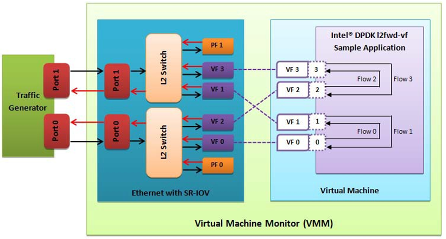
Fig. 34.2 Performance Benchmark Setup
34.4. DPDK SR-IOV PMD PF/VF Driver Usage Model
34.4.1. Fast Host-based Packet Processing
Software Defined Network (SDN) trends are demanding fast host-based packet handling. In a virtualization environment, the DPDK VF PMD performs the same throughput result as a non-VT native environment.
With such host instance fast packet processing, lots of services such as filtering, QoS, DPI can be offloaded on the host fast path.
Fig. 34.3 shows the scenario where some VMs directly communicate externally via a VFs, while others connect to a virtual switch and share the same uplink bandwidth.
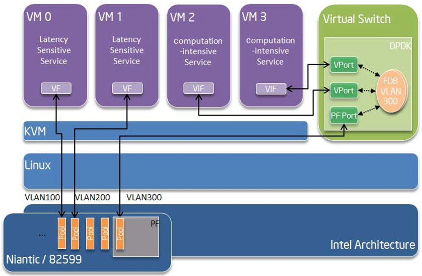
Fig. 34.3 Fast Host-based Packet Processing
34.5. SR-IOV (PF/VF) Approach for Inter-VM Communication
Inter-VM data communication is one of the traffic bottle necks in virtualization platforms. SR-IOV device assignment helps a VM to attach the real device, taking advantage of the bridge in the NIC. So VF-to-VF traffic within the same physical port (VM0<->VM1) have hardware acceleration. However, when VF crosses physical ports (VM0<->VM2), there is no such hardware bridge. In this case, the DPDK PMD PF driver provides host forwarding between such VMs.
Fig. 34.4 shows an example. In this case an update of the MAC address lookup tables in both the NIC and host DPDK application is required.
In the NIC, writing the destination of a MAC address belongs to another cross device VM to the PF specific pool. So when a packet comes in, its destination MAC address will match and forward to the host DPDK PMD application.
In the host DPDK application, the behavior is similar to L2 forwarding, that is, the packet is forwarded to the correct PF pool. The SR-IOV NIC switch forwards the packet to a specific VM according to the MAC destination address which belongs to the destination VF on the VM.
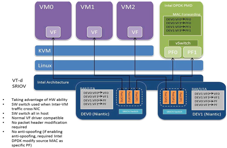
Fig. 34.4 Inter-VM Communication
34.6. Windows Support
IAVF PMD currently is supported only inside Windows guest created on Linux host.
Physical PCI resources are exposed as virtual functions into Windows VM using SR-IOV pass-through feature.
Create a Windows guest on Linux host using KVM hypervisor. Refer to the steps mentioned in the above section: Setting Up a KVM Virtual Machine Monitor.
In the Host machine, download and install the kernel Ethernet driver for i40e or ice.
For Windows guest, install NetUIO driver in place of existing built-in (inbox) Virtual Function driver.
To load NetUIO driver, follow the steps mentioned in dpdk-kmods repository.
34.7. Inline IPsec Support
IAVF PMD supports inline crypto processing depending on the underlying hardware crypto capabilities. IPsec Security Gateway Sample Application supports inline IPsec processing for IAVF PMD. For more details see the IPsec Security Gateway Sample Application and Security library documentation.
34.8. Diagnostic Utilities
34.8.1. Tx LLDP Testing
There are two methods to trigger LLDP packet transmission from the VF.
The first (and recommended) method is to set the packet_type of the mbuf
to RTE_PTYPE_L2_ETHER_LLDP.
This, in conjunction with enabling the enable_ptype_lldp devarg
will cause such packets to be transmitted:
-a 0000:xx:xx.x,enable_ptype_lldp=1
An alternative method is to register an mbuf dynfield IAVF_TX_LLDP_DYNFIELD
before dev_start.
This dynfield needs to be set to 1 when preparing an LLDP packet intended for transmission.
Note
The dynamic mbuf field method is deprecated and will be removed in a future release.
Users should migrate to the enable_ptype_lldp devarg and mbuf LLDP ptype method
described above.
For dpdk-testpmd application, the dynamic mbuf field is registered
when the following command is issued:
Usage:
testpmd> set tx lldp on
One must then stop and restart the port for it to take effect.
These requirements only apply for the dynamic mbuf field method;
no special steps are needed for the enable_ptype_lldp devarg method.
If both methods are enabled, the ptype based method will take precedence
over the dynamic mbuf field method.
34.9. Limitations or Knowing issues
34.9.1. 16 Byte RX Descriptor setting is not available
Currently the VF’s RX descriptor size is decided by PF. There’s no PF-VF interface for VF to request the RX descriptor size, also no interface to notify VF its own RX descriptor size. For all available versions of the kernel PF drivers, these drivers don’t support 16 bytes RX descriptor. If the Linux kernel driver is used as host driver, while DPDK iavf PMD is used as the VF driver, DPDK cannot choose 16 bytes receive descriptor. The reason is that the RX descriptor is already set to 32 bytes by the all existing kernel driver. In the future, if the any kernel driver supports 16 bytes RX descriptor, user should make sure the DPDK VF uses the same RX descriptor size.
34.9.2. i40e: VF performance is impacted by PCI extended tag setting
To reach maximum NIC performance in the VF the PCI extended tag must be enabled. But the kernel driver does not set this feature during initialization. So when running traffic on a VF which is managed by the kernel PF driver, a significant NIC performance downgrade has been observed (for 64 byte packets, there is about 25% line-rate downgrade for a 25GbE device and about 35% for a 40GbE device).
For kernel version >= 4.11, the kernel’s PCI driver will enable the extended tag if it detects that the device supports it. So by default, this is not an issue. For kernels <= 4.11 or when the PCI extended tag is disabled it can be enabled using the steps below.
Get the current value of the PCI configure register:
setpci -s <XX:XX.X> a8.w
Set bit 8:
value = value | 0x100
Set the PCI configure register with new value:
setpci -s <XX:XX.X> a8.w=<value>
34.9.3. i40e: Vlan strip of VF
The VF vlan strip function is only supported in the i40e kernel driver >= 2.1.26.
34.9.4. i40e: Vlan filtering of VF
For i40e driver 2.17.15, configuring VLAN filters from the DPDK VF is unsupported. When applying VLAN filters on the VF it must first be configured from the corresponding PF.
34.9.5. ice: VF inserts VLAN tag incorrectly on AVX-512 Tx path
When the kernel driver requests the VF to use the L2TAG2 field of the Tx context descriptor to insert the hardware offload VLAN tag, AVX-512 Tx path cannot handle this case correctly due to its lack of support for the Tx context descriptor.
The VLAN tag will be inserted to the wrong location (inner of QinQ) on AVX-512 Tx path. That is inconsistent with the behavior of PF (outer of QinQ). The ice kernel driver version newer than 1.8.9 requests to use L2TAG2 and has this issue.
Set the parameter –force-max-simd-bitwidth as 64/128/256 to avoid selecting AVX-512 Tx path.
34.9.6. ice: VLAN tag length not included in MTU
When configuring MTU for a VF, MTU must not include VLAN tag length. In practice, when kernel driver configures VLAN filtering for a VF, the VLAN header tag length will be automatically added to MTU when configuring queues. As a consequence, when attempting to configure a VF port with MTU that, together with a VLAN tag header, exceeds maximum supported MTU, port configuration will fail if kernel driver has configured VLAN filtering on that VF.
34.9.7. QinQ strip
QinQ TPID is set as 0x8100 IEEE 802.1Q by default. For QinQ strip with TPID 0x88A8 IEEE 802.1ad, extend VLAN is enabled and VLAN outer TPID is set to 0x88A8. VLAN filter steps can be added before or after.
To start testpmd, and enable QinQ strip for TPID 0x88A8 on port 0:
./<build_dir>/app/dpdk-testpmd -l 0-15 -- -i --forward-mode=mac
...

testpmd> vlan set extend on 0
testpmd> vlan set outer tpid 0x88A8 0
testpmd> vlan set qinq_strip on 0
For QinQ strip with TPID 0x8100, extend VLAN is enabled only.
To start testpmd, and enable QinQ strip for default TPID on port 0:
./<build_dir>/app/dpdk-testpmd -l 0-15 -- -i --forward-mode=mac
...

testpmd> vlan set extend on 0
testpmd> vlan set qinq_strip on 0
34.9.8. QinQ Configuration
When using QinQ Tx offload (RTE_ETH_TX_OFFLOAD_QINQ_INSERT),
you must also enable RTE_ETH_RX_OFFLOAD_VLAN_EXTEND
to configure the hardware for double VLAN mode.
Without this, only the inner VLAN tag will be inserted.
Example:
struct rte_eth_conf port_conf = {
    .rxmode = {
        .offloads = RTE_ETH_RX_OFFLOAD_VLAN_EXTEND,
    },
    .txmode = {
        .offloads = RTE_ETH_TX_OFFLOAD_QINQ_INSERT,
    },
};