53. Poll Mode Driver for Paravirtual VMXNET3 NIC
The VMXNET3 adapter is the next generation of a paravirtualized NIC, introduced by VMware* ESXi. It is designed for performance, offers all the features available in VMXNET2, and adds several new features such as, multi-queue support (also known as Receive Side Scaling, RSS), IPv6 offloads, and MSI/MSI-X interrupt delivery. One can use the same device in a DPDK application with VMXNET3 PMD introduced in DPDK API.
In this chapter, two setups with the use of the VMXNET3 PMD are demonstrated:
- Vmxnet3 with a native NIC connected to a vSwitch
- Vmxnet3 chaining VMs connected to a vSwitch
53.1. VMXNET3 Implementation in the DPDK
For details on the VMXNET3 device, refer to the VMXNET3 driver’s vmxnet3 directory and support manual from VMware*.
For performance details, refer to the following link from VMware:
http://www.vmware.com/pdf/vsp_4_vmxnet3_perf.pdf
As a PMD, the VMXNET3 driver provides the packet reception and transmission callbacks, vmxnet3_recv_pkts and vmxnet3_xmit_pkts.
The VMXNET3 PMD handles all the packet buffer memory allocation and resides in guest address space and it is solely responsible to free that memory when not needed. The packet buffers and features to be supported are made available to hypervisor via VMXNET3 PCI configuration space BARs. During RX/TX, the packet buffers are exchanged by their GPAs, and the hypervisor loads the buffers with packets in the RX case and sends packets to vSwitch in the TX case.
The VMXNET3 PMD is compiled with vmxnet3 device headers. The interface is similar to that of the other PMDs available in the DPDK API. The driver pre-allocates the packet buffers and loads the command ring descriptors in advance. The hypervisor fills those packet buffers on packet arrival and write completion ring descriptors, which are eventually pulled by the PMD. After reception, the DPDK application frees the descriptors and loads new packet buffers for the coming packets. The interrupts are disabled and there is no notification required. This keeps performance up on the RX side, even though the device provides a notification feature.
In the transmit routine, the DPDK application fills packet buffer pointers in the descriptors of the command ring and notifies the hypervisor. In response the hypervisor takes packets and passes them to the vSwitch, It writes into the completion descriptors ring. The rings are read by the PMD in the next transmit routine call and the buffers and descriptors are freed from memory.
53.2. Features and Limitations of VMXNET3 PMD
In release 1.6.0, the VMXNET3 PMD provides the basic functionality of packet reception and transmission. There are several options available for filtering packets at VMXNET3 device level including:
- MAC Address based filtering:
- Unicast, Broadcast, All Multicast modes - SUPPORTED BY DEFAULT
- Multicast with Multicast Filter table - NOT SUPPORTED
- Promiscuous mode - SUPPORTED
- RSS based load balancing between queues - SUPPORTED
- VLAN filtering:
- VLAN tag based filtering without load balancing - SUPPORTED
Note
- Release 1.6.0 does not support separate headers and body receive cmd_ring and hence, multiple segment buffers are not supported. Only cmd_ring_0 is used for packet buffers, one for each descriptor.
- Receive and transmit of scattered packets is not supported.
- Multicast with Multicast Filter table is not supported.
53.3. Prerequisites
The following prerequisites apply:
- Before starting a VM, a VMXNET3 interface to a VM through VMware vSphere Client must be assigned. This is shown in the figure below.
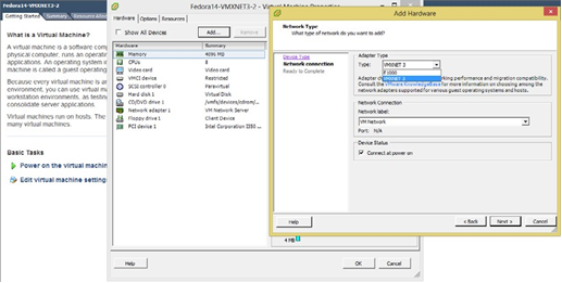
Fig. 53.4 Assigning a VMXNET3 interface to a VM using VMware vSphere Client
Note
Depending on the Virtual Machine type, the VMware vSphere Client shows Ethernet adaptors while adding an Ethernet device. Ensure that the VM type used offers a VMXNET3 device. Refer to the VMware documentation for a listed of VMs.
Note
Follow the DPDK Getting Started Guide to setup the basic DPDK environment.
Note
Follow the DPDK Sample Application’s User Guide, L2 Forwarding/L3 Forwarding and TestPMD for instructions on how to run a DPDK application using an assigned VMXNET3 device.
53.4. VMXNET3 with a Native NIC Connected to a vSwitch
This section describes an example setup for Phy-vSwitch-VM-Phy communication.
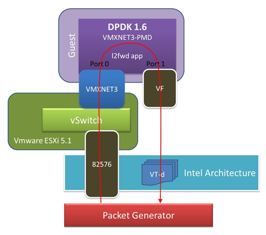
Fig. 53.5 VMXNET3 with a Native NIC Connected to a vSwitch
Note
Other instructions on preparing to use DPDK such as, hugepage enabling, uio port binding are not listed here. Please refer to DPDK Getting Started Guide and DPDK Sample Application’s User Guide for detailed instructions.
The packet reception and transmission flow path is:
Packet generator -> 82576
                 -> VMware ESXi vSwitch
                 -> VMXNET3 device
                 -> Guest VM VMXNET3 port 0 rx burst
                 -> Guest VM 82599 VF port 0 tx burst
                 -> 82599 VF
                 -> Packet generator
53.5. VMXNET3 Chaining VMs Connected to a vSwitch
The following figure shows an example VM-to-VM communication over a Phy-VM-vSwitch-VM-Phy communication channel.
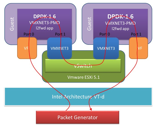
Fig. 53.6 VMXNET3 Chaining VMs Connected to a vSwitch
Note
When using the L2 Forwarding or L3 Forwarding applications, a destination MAC address needs to be written in packets to hit the other VM’s VMXNET3 interface.
In this example, the packet flow path is:
Packet generator -> 82599 VF
                 -> Guest VM 82599 port 0 rx burst
                 -> Guest VM VMXNET3 port 1 tx burst
                 -> VMXNET3 device
                 -> VMware ESXi vSwitch
                 -> VMXNET3 device
                 -> Guest VM VMXNET3 port 0 rx burst
                 -> Guest VM 82599 VF port 1 tx burst
                 -> 82599 VF
                 -> Packet generator