22. Load Balancer Sample Application
The Load Balancer sample application demonstrates the concept of isolating the packet I/O task from the application-specific workload. Depending on the performance target, a number of logical cores (lcores) are dedicated to handle the interaction with the NIC ports (I/O lcores), while the rest of the lcores are dedicated to performing the application processing (worker lcores). The worker lcores are totally oblivious to the intricacies of the packet I/O activity and use the NIC-agnostic interface provided by software rings to exchange packets with the I/O cores.
22.1. Overview
The architecture of the Load Balance application is presented in the following figure.
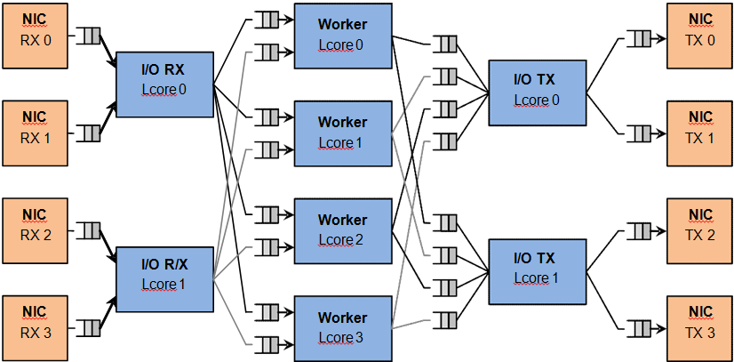
Fig. 22.1 Load Balancer Application Architecture
For the sake of simplicity, the diagram illustrates a specific case of two I/O RX and two I/O TX lcores off loading the packet I/O overhead incurred by four NIC ports from four worker cores, with each I/O lcore handling RX/TX for two NIC ports.
22.1.1. I/O RX Logical Cores
Each I/O RX lcore performs packet RX from its assigned NIC RX rings and then distributes the received packets to the worker threads. The application allows each I/O RX lcore to communicate with any of the worker threads, therefore each (I/O RX lcore, worker lcore) pair is connected through a dedicated single producer - single consumer software ring.
The worker lcore to handle the current packet is determined by reading a predefined 1-byte field from the input packet:
worker_id = packet[load_balancing_field] % n_workers
Since all the packets that are part of the same traffic flow are expected to have the same value for the load balancing field, this scheme also ensures that all the packets that are part of the same traffic flow are directed to the same worker lcore (flow affinity) in the same order they enter the system (packet ordering).
22.1.2. I/O TX Logical Cores
Each I/O lcore owns the packet TX for a predefined set of NIC ports. To enable each worker thread to send packets to any NIC TX port, the application creates a software ring for each (worker lcore, NIC TX port) pair, with each I/O TX core handling those software rings that are associated with NIC ports that it handles.
22.1.3. Worker Logical Cores
Each worker lcore reads packets from its set of input software rings and routes them to the NIC ports for transmission by dispatching them to output software rings. The routing logic is LPM based, with all the worker threads sharing the same LPM rules.
22.2. Compiling the Application
The sequence of steps used to build the application is:
Export the required environment variables:
export RTE_SDK=<Path to the DPDK installation folder>
export RTE_TARGET=x86_64-native-linuxapp-gcc
Build the application executable file:
cd ${RTE_SDK}/examples/load_balancer
make
For more details on how to build the DPDK libraries and sample applications, please refer to the DPDK Getting Started Guide.
22.3. Running the Application
To successfully run the application, the command line used to start the application has to be in sync with the traffic flows configured on the traffic generator side.
For examples of application command lines and traffic generator flows, please refer to the DPDK Test Report. For more details on how to set up and run the sample applications provided with DPDK package, please refer to the DPDK Getting Started Guide.
22.4. Explanation
22.4.1. Application Configuration
The application run-time configuration is done through the application command line parameters. Any parameter that is not specified as mandatory is optional, with the default value hard-coded in the main.h header file from the application folder.
The list of application command line parameters is listed below:
- –rx “(PORT, QUEUE, LCORE), ...”: The list of NIC RX ports and queues handled by the I/O RX lcores. This parameter also implicitly defines the list of I/O RX lcores. This is a mandatory parameter.
- –tx “(PORT, LCORE), ... ”: The list of NIC TX ports handled by the I/O TX lcores. This parameter also implicitly defines the list of I/O TX lcores. This is a mandatory parameter.
- –w “LCORE, ...”: The list of the worker lcores. This is a mandatory parameter.
- –lpm “IP / PREFIX => PORT; ...”: The list of LPM rules used by the worker lcores for packet forwarding. This is a mandatory parameter.
- –rsz “A, B, C, D”: Ring sizes:
- A = The size (in number of buffer descriptors) of each of the NIC RX rings read by the I/O RX lcores.
- B = The size (in number of elements) of each of the software rings used by the I/O RX lcores to send packets to worker lcores.
- C = The size (in number of elements) of each of the software rings used by the worker lcores to send packets to I/O TX lcores.
- D = The size (in number of buffer descriptors) of each of the NIC TX rings written by I/O TX lcores.
- –bsz “(A, B), (C, D), (E, F)”: Burst sizes:
- A = The I/O RX lcore read burst size from NIC RX.
- B = The I/O RX lcore write burst size to the output software rings.
- C = The worker lcore read burst size from the input software rings.
- D = The worker lcore write burst size to the output software rings.
- E = The I/O TX lcore read burst size from the input software rings.
- F = The I/O TX lcore write burst size to the NIC TX.
- –pos-lb POS: The position of the 1-byte field within the input packet used by the I/O RX lcores to identify the worker lcore for the current packet. This field needs to be within the first 64 bytes of the input packet.
The infrastructure of software rings connecting I/O lcores and worker lcores is built by the application as a result of the application configuration provided by the user through the application command line parameters.
A specific lcore performing the I/O RX role for a specific set of NIC ports can also perform the I/O TX role for the same or a different set of NIC ports. A specific lcore cannot perform both the I/O role (either RX or TX) and the worker role during the same session.
Example:
./load_balancer -l 3-7 -n 4 -- --rx "(0,0,3),(1,0,3)" --tx "(0,3),(1,3)" --w "4,5,6,7" --lpm "1.0.0.0/24=>0; 1.0.1.0/24=>1;" --pos-lb 29
There is a single I/O lcore (lcore 3) that handles RX and TX for two NIC ports (ports 0 and 1) that handles packets to/from four worker lcores (lcores 4, 5, 6 and 7) that are assigned worker IDs 0 to 3 (worker ID for lcore 4 is 0, for lcore 5 is 1, for lcore 6 is 2 and for lcore 7 is 3).
Assuming that all the input packets are IPv4 packets with no VLAN label and the source IP address of the current packet is A.B.C.D, the worker lcore for the current packet is determined by byte D (which is byte 29). There are two LPM rules that are used by each worker lcore to route packets to the output NIC ports.
The following table illustrates the packet flow through the system for several possible traffic flows:
| Flow # | Source IP Address | Destination IP Address | Worker ID (Worker lcore) | Output NIC Port |
|---|---|---|---|---|
| 1 | 0.0.0.0 | 1.0.0.1 | 0 (4) | 0 |
| 2 | 0.0.0.1 | 1.0.1.2 | 1 (5) | 1 |
| 3 | 0.0.0.14 | 1.0.0.3 | 2 (6) | 0 |
| 4 | 0.0.0.15 | 1.0.1.4 | 3 (7) | 1 |
22.4.2. NUMA Support
The application has built-in performance enhancements for the NUMA case:
- One buffer pool per each CPU socket.
- One LPM table per each CPU socket.
- Memory for the NIC RX or TX rings is allocated on the same socket with the lcore handling the respective ring.
In the case where multiple CPU sockets are used in the system, it is recommended to enable at least one lcore to fulfill the I/O role for the NIC ports that are directly attached to that CPU socket through the PCI Express* bus. It is always recommended to handle the packet I/O with lcores from the same CPU socket as the NICs.
Depending on whether the I/O RX lcore (same CPU socket as NIC RX), the worker lcore and the I/O TX lcore (same CPU socket as NIC TX) handling a specific input packet, are on the same or different CPU sockets, the following run-time scenarios are possible:
- AAA: The packet is received, processed and transmitted without going across CPU sockets.
- AAB: The packet is received and processed on socket A, but as it has to be transmitted on a NIC port connected to socket B, the packet is sent to socket B through software rings.
- ABB: The packet is received on socket A, but as it has to be processed by a worker lcore on socket B, the packet is sent to socket B through software rings. The packet is transmitted by a NIC port connected to the same CPU socket as the worker lcore that processed it.
- ABC: The packet is received on socket A, it is processed by an lcore on socket B, then it has to be transmitted out by a NIC connected to socket C. The performance price for crossing the CPU socket boundary is paid twice for this packet.